The Edgebands section defines edge banding and finishing operations, such as grinding, that can be assigned to individual edges of plan parts.
Go to the Edgebands tab (Ctrl+5 or File > Inventory > Edgebands) and press Ins to add a definition.
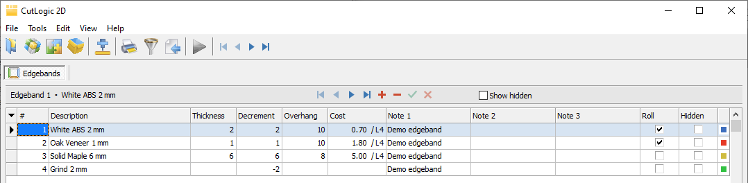
Once defined, edgebands can be assigned to any applicable edge of a part in Plans > Parts using the part detail panel (F5). Banding decrements affect net cutting dimensions; the required banding length and cost can also be included in reports and exports. For assigning edges, see Plan parts.
Edgeband fields
•# - Automatically assigned number, used for default sorting.
•Description - Name of the edgeband or finishing operation.
•Thickness - Thickness of the edgeband.
•Decrement - Amount subtracted from the entered part Length or Width for each banded edge when calculating Net length or Net width, the dimensions used for cutting. This compensates for edge banding so the finished part matches the entered dimensions. Negative decrements increase the cutting dimensions, for example to allow for grinding.
•Overhang - Additional banding length beyond the part edge, included when calculating the required banding length.
•Cost - Banding cost per length unit, using L1, L2, L3, L4, or L9 for 1, 10, 100, 1,000, or 12 length units, respectively.
•Note 1-4 - Optional additional information.
•Roll - Identifies banding supplied in rolls; used in edge-banding previews, reports, and exports.
•Hidden - Hides a definition that is no longer normally used without deleting it. Enable Show hidden to display hidden definitions.
•Color - Color used to identify the edgeband in the program.
•ID - Unique, automatically generated, read-only identifier.
To show, hide, or reorder columns, select View > Rearrange columns.