To open Machines, select File > Machines or press Ctrl+6.
Machines allows you to configure CNC machines and generate G-code from the optimized cutting layouts of the currently selected plan in File > Plans. It supports cutting, engraving, and marking with routers, lasers, and other CNC equipment. Depending on the selected machine type and function, you can optimize toolpaths, add leads and tabs, cut in multiple passes, and engrave or mark text on parts.
Each machine definition contains machining parameters, G-code blocks, and export settings. You can create several definitions for the same physical machine, for example for different materials, tools, or cutting and engraving operations.
CutLogic 2D automatically generates the toolpath commands and combines them with customizable G-code blocks inserted at the beginning and end of the program and before and after each cutting sequence. These blocks let you adapt the output to your controller and machining process, including spindle or laser control, coolant, and other machine-specific commands.
To get started, modify a sample machine definition or select it and press Ctrl+V to create a copy. Adjust its settings and G-code blocks to match your equipment. Use Preview G-code to inspect the generated program, then Export G-code to save it for transfer to your CNC machine.
Safety warning: Before running generated G-code on a CNC machine, verify that the code and machine settings are correct. Test new or modified machine configurations carefully, preferably using simulation or a dry run. Incorrect settings or G-code can damage equipment or cause injury. Follow the machine manufacturer's safety instructions.
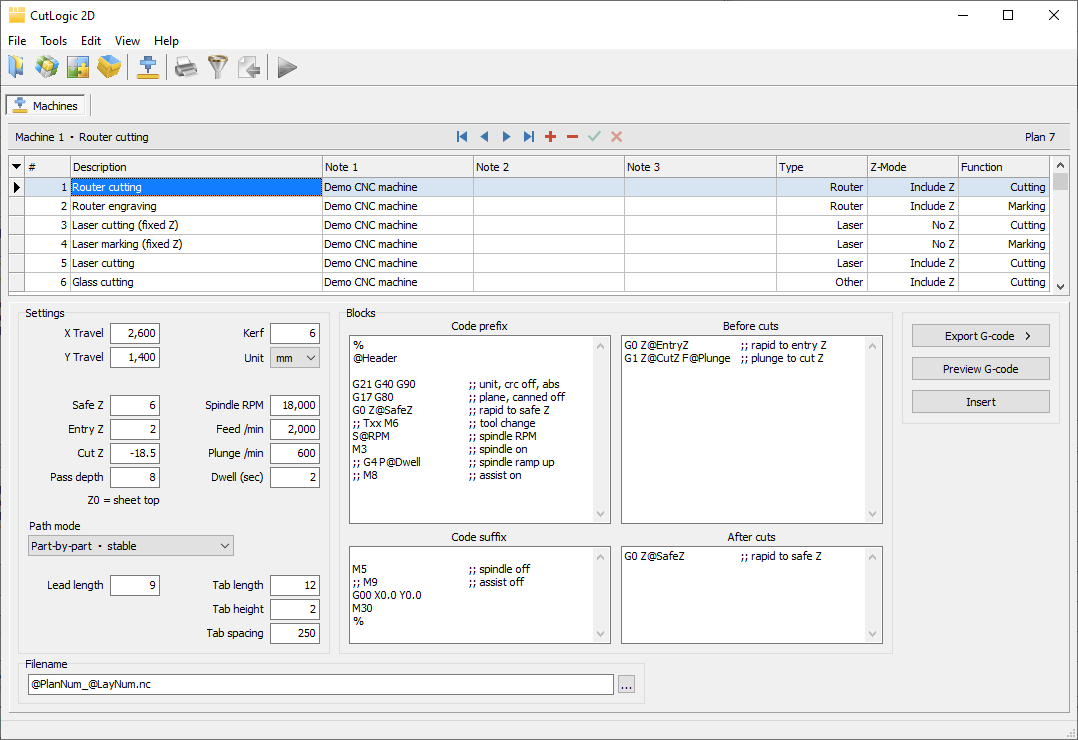
Router cutting
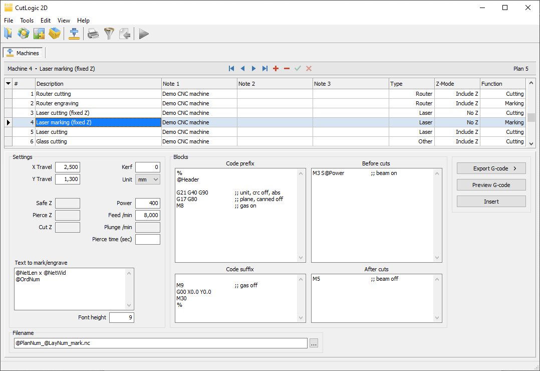
Laser marking (fixed Z)
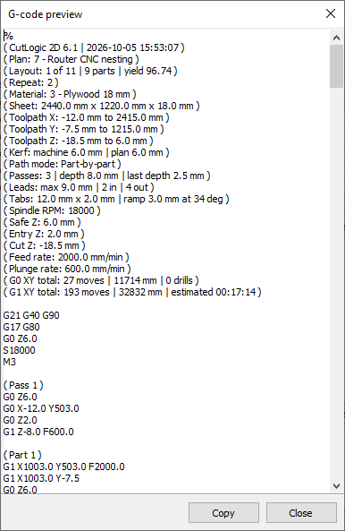
Generated G-code for router cutting
Machine fields
#
Number assigned automatically when a machine is added. The machine list is sorted by this number by default. You can change the numbers to arrange machines in your preferred order.
Description
Unique machine name. Use a name that identifies the intended operation, such as Router cutting or Laser marking.
Note 1-4
Optional notes about the machine, material, tool, or operating settings.
Type
Machine type: Router, Laser, or Other. The type determines the applicable settings and their interpretation. Use Other for equipment such as glass cutters, fabric cutters, or dot-peen marking machines, with settings and G-code blocks adapted to the controller and operation.
Z-Mode
Controls the use of the Z axis:
•No Z: For operations that do not require Z-axis positioning, such as cutting or marking with a fixed-height laser.
•Include Z: For operations that require Z-axis positioning, such as router cutting and engraving.
•Smart Z: For machines whose controller handles all necessary pre-cut and post-cut actions through commands such as M3 and M5. These actions include Z positioning, probing, power control, and lifting to Safe Z. The G-code blocks therefore need only the corresponding controller commands.
For routers, only Include Z is available.
Function
Select Cutting to cut parts or Marking to mark or engrave text. Cutting displays the path, lead, and tab settings. Marking displays Text to mark/engrave and Font height instead.
Line break
Line ending used in the generated file: CRLF (default), CR, or LF. Change it if your controller requires another format.
To show, hide, or reorder columns, select View > Rearrange columns.
X Travel / Y Travel
Available machine travel along the X and Y axes. Set these values to match the usable working area of the machine.
Kerf
Actual cutting width of the tool or beam. For a router, this is normally the cutter diameter. For a laser, use the cutting width produced by the selected material and operating settings.
The machine kerf and the plan kerf serve different purposes: the plan kerf determines spacing in the optimized layout, while the machine kerf describes the actual cut. The following requirements apply when cutting:
Path mode |
Kerf requirement |
Connected, Part-by-part, Guillotine |
Machine kerf must equal plan kerf |
Skeleton |
Plan kerf must be greater than twice the machine kerf |
See Preparing the cutting plan below.
Kerf is ignored when Function is Marking. You may still enter the expected width of the engraved or marked line for reference.
Unit
Length unit, mm or in, used for the machine settings and generated G-code. Ensure that the controller's unit selection in the G-code blocks agrees with this setting.
Safe Z
Z position for clearance during travel between cuts. Choose a position that clears the workpiece and any fixtures crossed by the tool.
Pierce Z / Entry Z
Pierce Z is the Z position at which the beam pierces the material before cutting begins. For router operations, Entry Z is the position above the workpiece from which the tool begins its controlled plunge. Keeping Entry Z close to the surface can reduce unnecessary plunge time, provided there is sufficient clearance.
Cut Z
Z position used for cutting or engraving. For example, when work zero is at the top of the sheet, a negative router Cut Z represents a depth below the top surface.
Z positions are relative to the work zero (Z0) used for the operation. For single-pass operations, Z0 may be at either the sheet top or the sheet bottom, provided the Z settings match that reference.
Pass depth
Depth removed in each pass. Leave empty for a single pass, or enter a positive value to enable multi-pass cutting. Multi-pass cutting requires Z0 at the sheet top. The final pass reaches Cut Z and may be shallower than the preceding passes.
A shallow final pass allows a thin skin to hold the parts in place during earlier passes. For example, Cut Z = -6 mm and Pass depth = 5.5 mm leave a 0.5 mm skin to be removed in the final pass.
Spindle RPM / Power
Spindle RPM sets the spindle speed for Router machines. Power sets the operating power for Laser and Other machines. Power values must use the scale expected by the controller; they are not necessarily percentages.
Feed /min
Feed rate for cutting or marking moves, expressed in the selected length unit per minute.
Plunge /min
Feed rate for the controlled Z movement into the material, expressed in the selected length unit per minute.
If you add G95 to Code prefix, the labels change to Feed /rev and Plunge /rev; enter the rates per spindle revolution instead. This mode requires controller support.
Dwell (sec) / Pierce time (sec)
Pause duration in seconds, used by the corresponding commands in the G-code blocks. Typical uses include allowing a router spindle to reach speed or allowing a laser to pierce the material before cutting begins.
Use @Dwell in G-code blocks for seconds, or @DwellMS if the controller requires milliseconds. Enter the value in this field in seconds in either case.
The following four G-code blocks contain controller commands used before and after the cutting or marking moves generated by CutLogic 2D. They determine how settings such as spindle speed, power, Z positions, and pauses are applied. Tokens in these blocks are replaced with the corresponding values when G-code is generated. The default blocks serve as templates that you can adapt to your controller.
Code prefix
Code placed at the beginning of the generated program. Typical uses include the header, unit and positioning modes, and machine initialization.
Code suffix
Code placed at the end of the generated program. Typical uses include switching off the spindle or beam, moving to a finishing position, and ending the program.
Before cuts
Code executed before a cutting or marking sequence. Typical uses include positioning in Z, setting power, switching on the tool or beam, and piercing or plunging.
After cuts
Code executed after a cutting or marking sequence. Typical uses include switching off the beam or retracting the tool before travel to the next sequence.
See G-code blocks, tokens, and customization for further information.
Path mode
Select how CutLogic 2D generates the cutting paths:
Connected |
Connects cuts to reduce interruptions and travel. Useful when cutting efficiency is the main priority and the material is held securely. |
Part-by-part |
Cuts parts in sequence. A useful general-purpose choice when the order in which parts are released matters. Use Snake layout part order for an efficient sequence. |
Guillotine |
Follows the guillotine cutting structure. Suitable for glass and other operations requiring guillotine cuts. |
Skeleton |
Creates a separate cutting frame around each part, leaving a surrounding skeleton. Useful when additional support during cutting is needed. |
See Choosing a cutting strategy for guidance on holding parts and combining these modes with tabs or multi-pass cutting.
Lead length
Controls lead extensions at the start and end of cuts and limits how far cuts may extend into plan trims, including remnant-separation cuts. Leads can start or end in air, trim, or waste. Leave empty for no leads.
The actual lead length depends on the path mode and available space. Lead-outs are half the corresponding lead-in length. See Leads and minimizing piercing for further details.
Tab length
Length of the small connections left along part edges to help hold parts in place during cutting. Leave empty for no tabs.
Router tabs have a trapezoidal profile: the tool rises towards the tab, passes across its top, and descends back to the cutting depth.
Tab height / Tab power
For router cutting, Tab height determines the thickness of material left at a tab. For Laser and Other machines, Tab power specifies the power used while crossing a tab.
Tab spacing
Controls the spacing between tabs along the cutting path. Leave empty to place a single tab on each part edge. Choose spacing appropriate to the part size, material, and holding method.
When a very narrow strip separates adjacent part edges, tabs on those edges are automatically aligned to help prevent the strip from bending and improve stability during cutting.
Text to mark/engrave
Text placed on parts. You can enter literal text, tokens, or a combination of both. Typical uses include part sizes, order numbers, and other part or plan information.
Only ASCII text is supported. This restriction also applies to text supplied by tokens; accented letters and other non-ASCII characters are not supported.
Click Insert or press F2 to select tokens from the token list.
Font height
Height of the marked or engraved text, expressed in the selected length unit. Choose a height suitable for the available space and the line width produced by the tool or beam.
Filename
Name or full path of the exported G-code files. Tokens can identify the plan and layout automatically.
The default patterns are:
•Cutting: @PlanNum_@LayNum.nc
•Marking: @PlanNum_@LayNum_mark.nc
Add a destination folder to avoid the folder-selection dialog, for example:
C:\CNC\@PlanNum_@LayNum.nc
Set Filename to COM to export G-code directly to a physical or virtual serial port.