The DXF export tab controls the content and appearance of exported cutting layout drawings. You can select the objects to export, assign them to layers, configure part information, and enable automatic export after optimization.
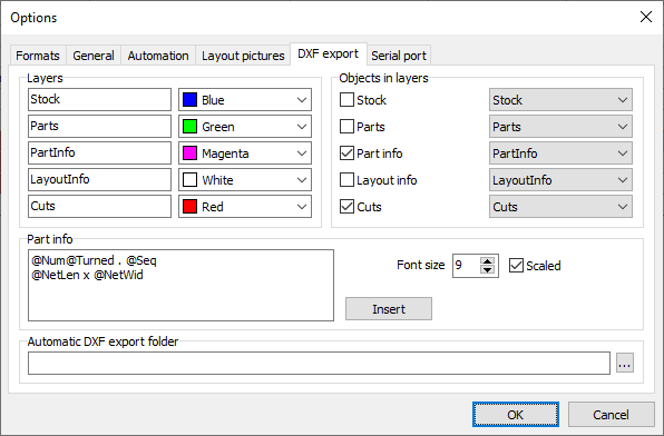
Layers
Define the layer names and colors used in DXF files. Separate layers make it easier to show, hide, or process different elements in a CAD application.
Objects in layers
Select which objects to include: Stock, Parts, Part info, Layout info, and Cuts. For each enabled object type, choose the layer it will be assigned to.
Part info
Define the text included with parts when Part info is enabled. You can combine ordinary text with tokens, which are replaced by the corresponding values from the part, plan, or material. Click Insert to select an available token.
Each line in the text box becomes a separate line of part information.
Font size: Sets the size of the exported text.
Scaled: When checked, the font size is interpreted relative to the layout, using its appearance on a Full HD screen as a reference. When unchecked, the font size specifies an absolute text size in millimeters in the DXF file.
Automatic DXF export folder
Specify an output folder to export cutting layouts automatically after each optimization. Leave this field empty to disable automatic export.
You can also export manually through File > Export > Export cutting layouts to DXF files. Each cutting layout is exported to a separate file.