The Layout pictures tab controls the information and colors shown in cutting layout pictures. Use In program and In reports to configure the two outputs separately.
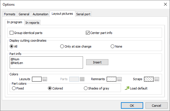
Part display
Group identical parts: Displays shared information for grouped identical parts instead of repeating the information for each part.
Center part info: Centers the information within each part. When unchecked, the information is aligned to the left.
Display cutting coordinates: Select how cutting coordinates are shown:
•All: Shows all cutting coordinates.
•Only at size change: Shows coordinates only where the part size changes.
•None: Hides cutting coordinates.
Part info
Define the text displayed in parts. You can combine ordinary text with tokens, which are replaced by the corresponding values from the part, plan, or material. Click Insert to select an available token.
For example:
@Num
@NetLen
This displays the part number on the first line and its net length on the second. Add or remove lines to choose how much information appears in each part.
Colors
Set the colors used for Layouts, Parts, Remnants, and Scraps.
Part colors: Select how parts are colored:
•Fixed: Uses the selected Parts color for all parts.
•Colored: Uses individual part colors.
•Shades of gray: Displays parts in shades of gray.
Click Load default to restore the default colors.